| Sign In | Join Free | My hardware-wholesale.com |
|
- Home
- Products
- About Us
- Quality Control
- Contact Us
- Get Quotations
| Sign In | Join Free | My hardware-wholesale.com |
|
Brand Name : Suntor
Model Number : ST1410KP
Place of Origin : ShenZhen
MOQ : 1 Set
Payment Terms : T/T, Western Union
Supply Ability : 1000 Set per month
Delivery Time : 15 work days
Packaging Details : box package
Color : White
Weight : 160g
Dimensions : 130*55*25mm
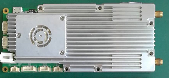
ST1410KP wireless IP digital transmission module is a wireless transmission product designed on the basis of the self-developed OFDM baseband algorithm. It has the characteristics of large bandwidth, long distance, strong anti-interference ability, strong diffraction performance and so on.

key technology
Applicable scene

| Wireless Specifications | ||||||
| Frequency range | 1410~1470MHz | |||||
| Carrier modulation | OFDM | |||||
| RF channel | 2*Tx & 2*Rx | |||||
| Baseband protocol | independent intellectual property | |||||
| Code rate | 1.2Mbps | 2.5Mbps | 5Mbps | 7Mbps | 9Mbps | 13Mbps |
| RF Bandwidth | 4MHz | 8MHz | 8MHz | 10MHz | 14MHz | 20MHz |
| Constellation modulation | QPSK | QPSK | QPSK | QPSK | QPSK | QPSK |
| RF power | 2*25dbm | 2*25dbm | 2*25dbm | 2*25dbm | 2*25dbm | 2*25dbm |
| Receiving sensitivity | -106dBm | -104dBm | -99dBm | -98dBm | -96dBm | -95dBm |
| Note: the detailed code rate is described below | ||||||
| Data Specifications | ||||||
| Ethernet data | 1.2Mbps~13Mbps One-way | |||||
| Control data | 115Kbps Two-way | |||||
| Safety | ||||||
| Encryption standard | AES 128bit; Physical layer encryption | |||||
| Interface | ||||||
| Ethernet | One-way Wide bandwidth data; Two-way115Kbps,UDP protocol | |||||
| Serial port | 115Kbps two-way | |||||
| Voltage and power dissipation | 9~24V <15W | |||||
Interface definition

Interface definition sheet 1
| number | Interface name | Interface description |
| 1 | DC 12V | power supply interface,typical DC 12V |
| 2 | Ethernet Interface | Standard 4 core network interface |
| 3 | Debug | USB to serial port,monitoring the use of printing information |
| 4 | Switch | 1 Switch 1,ON is Receiver,OFF is Transmitter 2 Switch 2,reserve,Dial to KE
note:The Receiver and Transmitter share hardware, and the working state is selected through this dialing switch. |
| 5 | LED | 1 Running indicator 2Synchro indicator 3 Ethernet indicator |
| 6 | ANT1 | Antenna interface,Tx1 & Rx1,SMA-Female |
| 7 | ANT2 | Antenna interface,Tx2 & Rx2,SMA-Female |
1.2 Detailed definition of Tube Foot
| Number | Pin | Signal name | Signal description | Interface description | socket | Silk-screen |
| 1 | LED_ARM | Running indicator | LED light | |||
| LED_LINK | Wireless connection indicator | |||||
| LED_ACT | Ethernet Interface indicator | |||||
| 2 | 1 | GORA | Dial to the "ON" end to select the Receiver | Receiver and Transmitter selector switches | ||
| 2 | REV_SEL | reserve | ||||
| 3 | 1 | VBUS | Usb Power | Usb to uart Debug Interface | Micro straight USB socket | |
| 2 | USB_DN | Usb data | ||||
| 3 | USB_DP | |||||
| 4 | Suspension | |||||
| 5 | GND | Ground | ||||
| 4 | 1 | TPTX+ | Ethernet Interface data | Ethernet Interface | Straight 1.25mm space 4 Pin SMD socket | Ethernet |
| 2 | TPTX- | |||||
| 3 | TPRX+ | |||||
| 4 | TPRX- | |||||
| 5 | 1 | RX+ | RS485/422vdata | RS485/422 | Straight 1.25mm space 4 Pin SMD socket | RS485 |
| 2 | RX- | |||||
| 3 | TX+ | |||||
| 4 | TX- | |||||
| 6 | 1 | VCC12V_IN | 9v-24v power input | power | Crooked 2.0mm space 2 Pin through socket | DC12V |
| 2 | GND | Power ground | ||||
| 7 | 1 | GND | Fan signal ground | Fan Interface | Straight 1.25mm space 2 Pin SMD socket | 12V- |
| 2 | VCC12V_FAN | Fan 12v power | 12v+ | |||
| 8 | 1 | GPS_PP1S | pp1s Signal | GPS moduel interface | Straight 1.25mm space 6 Pin SMD socket | GPS |
| 2 | GND | ground | ||||
| 3 | GPS_UART_RX | Uart signal | ||||
| 4 | GPS_UART_TX | |||||
| 5 | VCC3V3 | power | ||||
| 6 | Reserve, Connect the ground or 3.3v power | |||||
| 9 | 1 | TX_232 | RS232 Transmit | RS232 | Straight 1.25mm space 4 Pin SMD socket | RS232 |
| 2 | GND | ground | ||||
| 3 | RX_232 | RS232 receive | ||||
| 4 | Suspension | |||||
| 10 | 1 | SYNC_IN | synchronization interface input | synchronization interface | Straight 1.25mm space 2 Pin SMD socket | SYNC |
| 2 | SYNC_OUT | synchronization interface output | ||||
| 11 | 1 | TRX2 | RF TX2/RX2 | Antenna interface | SMA | TX2 |
| 12 | 1 | TRX1 | RF TX1/RX1 | SMA | TX1 |
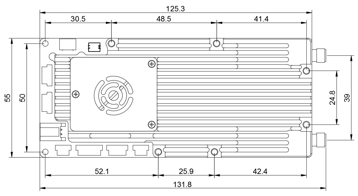
1.3 Mechanical specifications
| Mechanical specifications | |
| Dimensions | 125.3´55x15.7mm |
| Weight | 160 g |
| Working temperature | -40℃~+70℃ |
| installation drawing | (See the following figure) |

|
|
Drone Video&Data Transmission Module More Than 30KM UAV Links Images |